Product overview
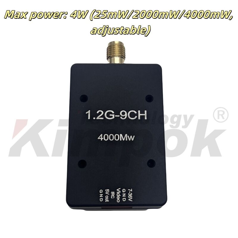
The Kimpok 1.2G 4W VTX is a wireless FPV video transmitter for racing-drone integration. Its nine selectable channels cover 1080MHz–1360MHz, with adjustable transmission settings of 25mW, 2000mW and 4000mW, plus Pit Mode. The hardware combines an aluminum alloy enclosure, heat sink and fan, with an SMA female antenna connection. Local buttons change band/channel and power, while separate red, blue and green LEDs indicate channel, band and power status. IRC Tramp provides a further control interface.
Installation requires space for a 53mm × 28.85mm × 16mm module, a 20mm × 20mm mounting pattern with 2mm holes, and ventilation around the cooling assembly. The six-pin connector carries supply power, grounds, video, IRC control and a 5V output; input power is DC 7V–36V with 2–8S battery support. Weight is specified inconsistently as 16g and 25.85g, without a configuration distinction. Above 100°C, protection progressively reduces output to 25mW; the original setting returns below 95°C. The antenna must be installed before power is applied.
Specifications
| Specification | Value & conditions |
|---|---|
| Place of origin | China |
| Brand | Kimpok |
| Certification | CE certification |
| Model | 1.2G 4W VTX |
| Documentation | 1.2G 4W VTX Manual.pdf |
| RF power | 4W |
| Channel count | 9CH |
| Frequency range | 1080MHz-1360MHz |
| Power supply | DC 7-36V 2-8S |
| Product specification weight | 16g |
| Band and channel range | 1.2GHz 9CH: 1080MHz-1360MHz |
| Maximum power and selectable levels | 4W (25mW/2000mW/4000mW, adjustable)Adjustable transmission power. |
| Input voltage | DC 7V-36VSupports 2-8S battery input. |
| Mounting hole spacing | 20mm*20mm/ø2mm |
| Dimensions | 53mm*28.85mm*16mm |
| Technical specification weight | 25.85g |
| Antenna connector | SMA female socket with inner hole |
| Control protocol | IRC Tramp |
| Cooling architecture | Aluminum alloy shell, heat sink and fan |
| Status indicators | Red channel LED; blue band LED; green power LED |
| Local controls | Band/channel change button and power change button |
| Power connector | 1.0 6P |
| Channel flash patterns | CH1–CH9 correspond respectively to 1–9 flashesChannel indication by red LED. |
| Power flash patterns |
|
| Temperature protection | Incremental power reduction to 25mW, with automatic restoration of the original settingTemperature exceeds 100°C; original power setting resumes below 95°C. |
| Channel frequencies |
|
| Pin assignments and wire colors |
|
| Ventilation requirement | Provide ventilation around the module to prevent overheating and power reductionDuring module operation. |
| Voltage and polarity requirement | Check supply voltage range and polarity to avoid component damageBefore powering on. |
| Antenna installation requirement | Install the antenna before applying powerBefore powering on. |