Product overview
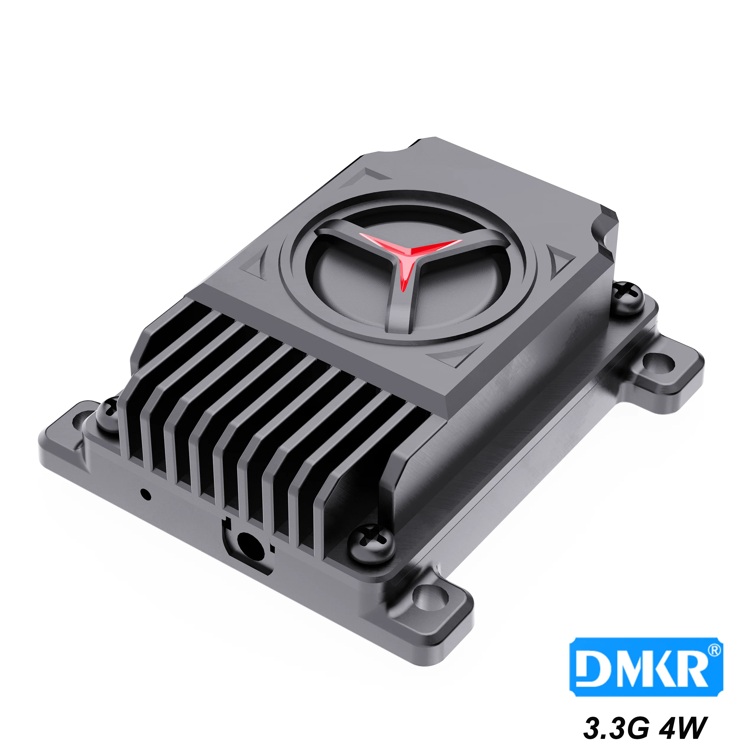
The Kimpok KP-T3350 is an FPV video transmitter for integration into a UAV, with 16 channels covering 3170MHz-3470MHz. Its two selectable output settings are 25mW and 5000mW, with a maximum rating of 5W. The module accepts DC 7V-36V and supports 2-8S battery input. An MCX connector provides the antenna interface, while IRC Tramp provides the specified control protocol. Local adjustment uses a band/channel button and a separate power button, supported by red channel, blue band and green power indicators.
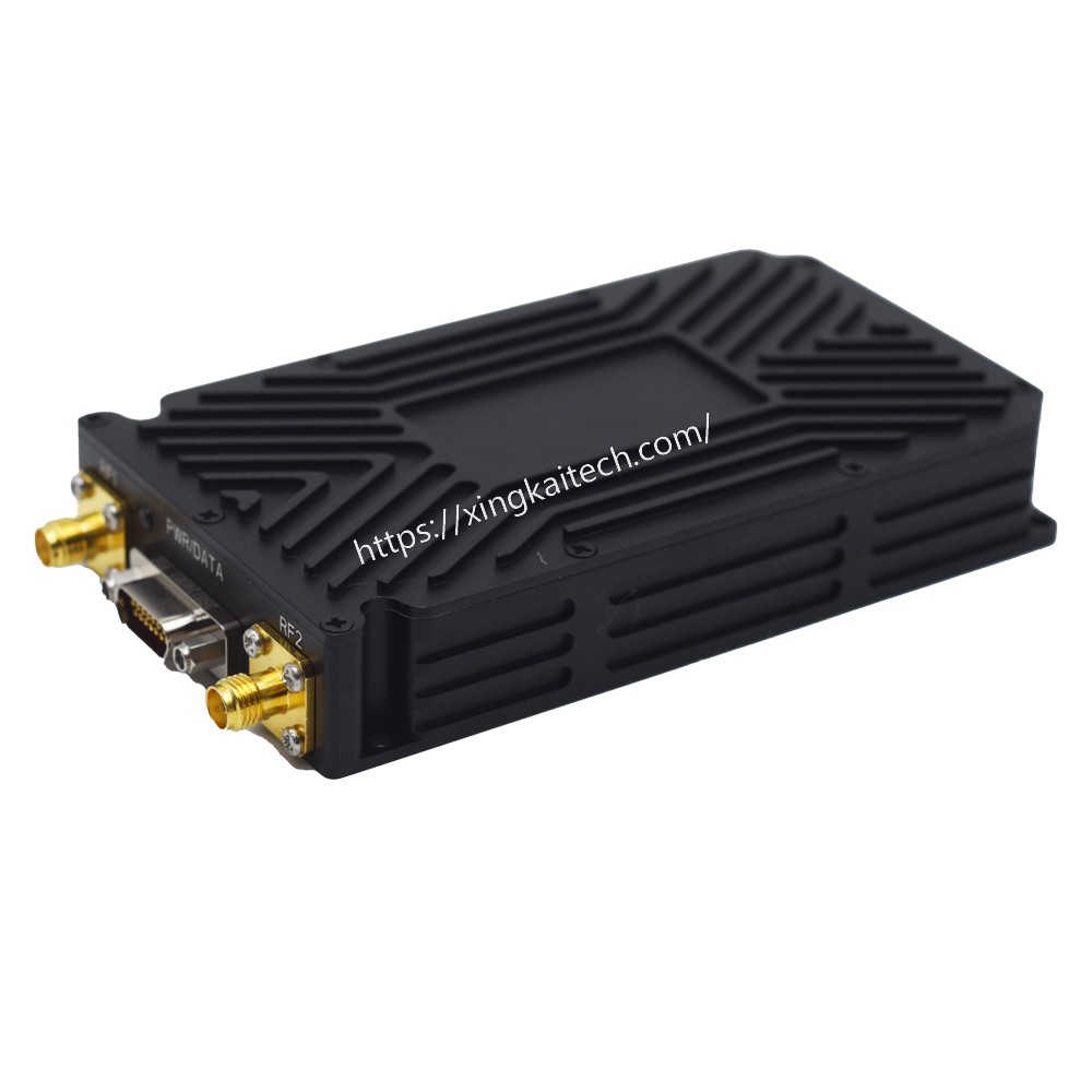
The physical assembly combines an aluminum alloy shell, heat sink and cooling fan in a 38mm*38mm*20.7mm envelope. Mounting uses 30.5mm*30.5mm hole spacing with ø3.0mm holes; the connection provisions include a 1.0 6P power connector and a cooling fan power cable holder. Installation must leave room for air convection around the module. Inadequate cooling can trigger reduced transmission power or transmission shutdown. Before applying power, the supply voltage and polarity should be checked and an antenna fitted to the RF output.
Specifications
| Specification | Value & conditions |
|---|---|
| Country of origin | China |
| Brand | Kimpok |
| Certification | CE certification |
| Model | KP-T3350 |
| Product type | Wireless video transmitter |
| Frequency range and channels | 3.3G; 3170MHz-3470MHz; 16 channels |
| RF output power | Maximum 5W; selectable 25mW/5000mWTwo adjustable power levels. |
| Input voltage | DC 7V-36VSupports 2-8S battery input. |
| Antenna connector | MCX |
| Control protocol | IRC Tramp |
| Cooling architecture | Aluminum alloy shell, heat sink and fan |
| Mounting hole spacing and diameter | 30.5mm*30.5mm /ø3.0mm |
| Dimensions | 38mm*38mm*20.7mm |
| Weight | 38 (unit unspecified) |
| Channel indicator | Red LED |
| Band indicator | Blue LED |
| Power indicator | Green LED |
| Local controls | Band and channel changer button; power changer button |
| Power connector | 1.0 6P |
| Fan cable provision | Cooling fan power cable holder |
| Installation airflow requirement | Requires clearance around the module for convective coolingInstalled with space for air convection around the module. |
| Thermal protection behavior | Reduces transmission power or shuts transmission downInsufficient heat dissipation causes overheating protection to activate. |
| Electrical connection precautions | Check supply voltage and polarity to avoid component damageBefore powering on. |
| Antenna installation recommendation | Fit an antenna to the RF output before applying powerBefore powering on. |