Product overview
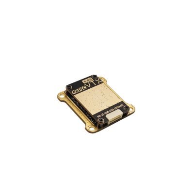
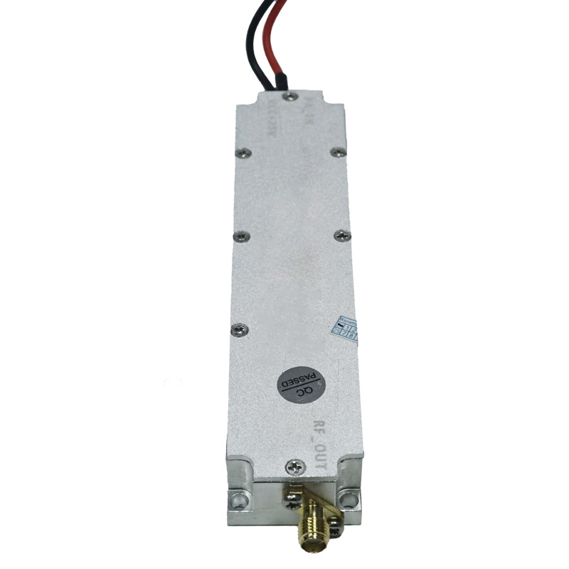
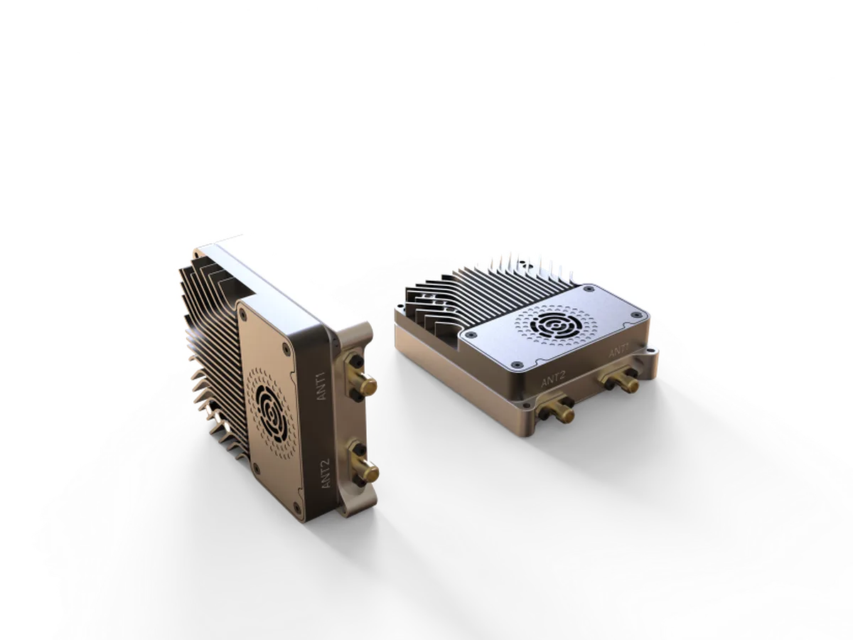
The Kimpok KP-T1245 is a wireless video transmitter module for FPV drone flight, racing and aerial photography. Its architecture combines FM transmission with PLL frequency control, a built-in aluminum heat sink and a fan for active cooling. The approximately 38.8 g module occupies 48.5 × 35 × 21.5 mm, giving integrators a defined component envelope for installation. Its 16 channels are arranged across two eight-channel groups within 1080–1360 MHz, with selectable output settings from PIT through 4.5 W.
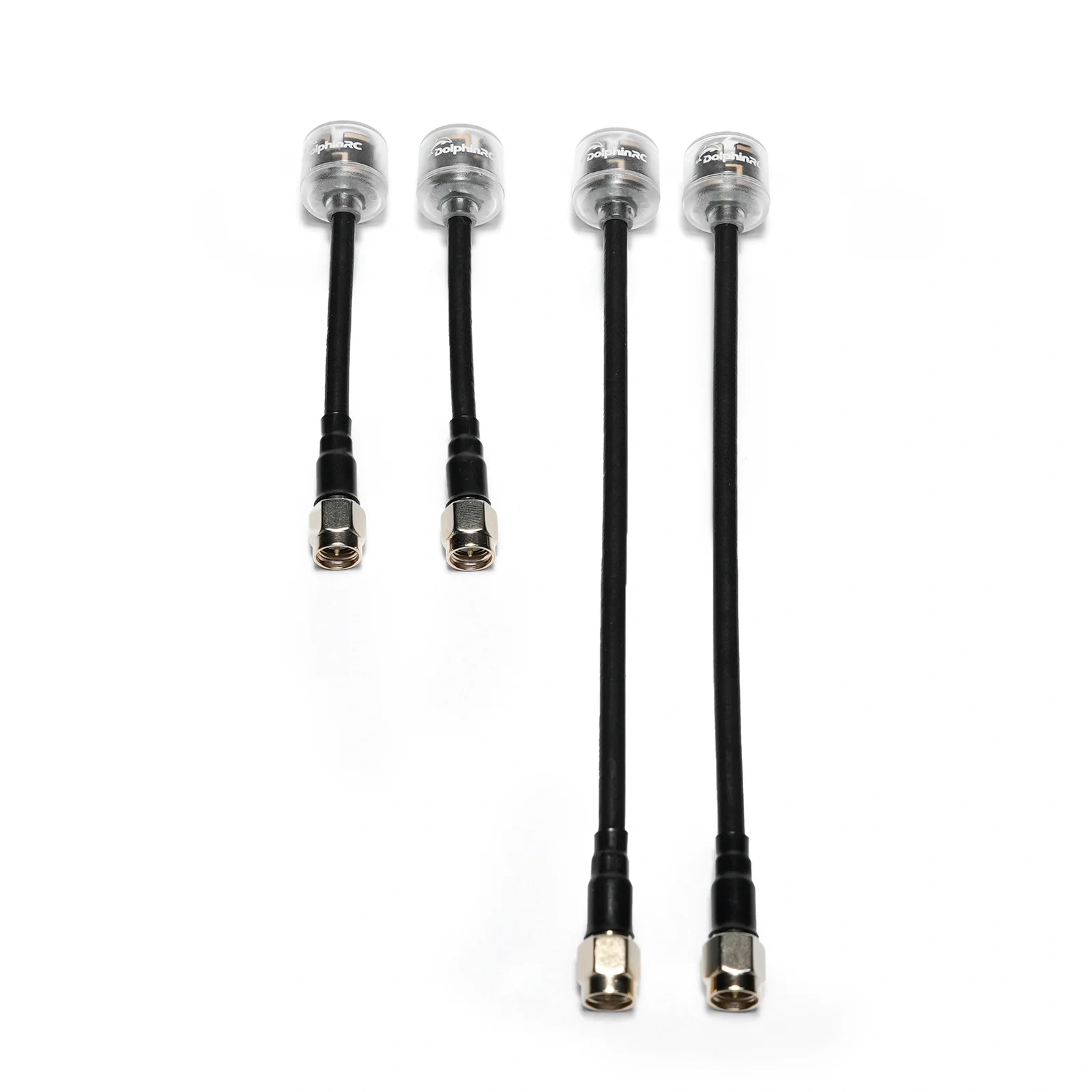
Integration connections comprise DC power input, two grounds, a 5V output, CVBS video input, an IRC control input and an SMA antenna port. IRC supports channel and power adjustment, including OSD parameter adjustment. Power input must remain within DC 7–30V with correct polarity, and the RF antenna must be fitted correctly before power-on to avoid damage. Temperature protection accompanies the active cooling, while the operating range is -10°C to +60°C. The transmitter surface can become hot during use and should not be touched directly.
Specifications
| Specification | Value & conditions |
|---|---|
| Manufacturer and model | Kimpok KP-T1245 |
| Place of origin | China |
| Certification | CE |
| Input voltage | DC +7V~30V |
| Output voltage | DC +5V |
| Frequency band | 1080–1360 MHz |
| Channel count | 16 |
| Channel frequencies | Band A, channels 1–8: 1080/1120/1160/1200/1240/1280/1320/1360 MHz; Band B, channels 1–8: 1080/1120/1160/1200/1258/1280/1320/1360 MHz |
| Modulation | FM |
| Frequency control | PLL |
| Frequency stability | ±100 KHzTypical. |
| Frequency precision | ±200 KHzTypical. |
| Signal-to-noise ratio | Greater than 55 dBcFo ±3 MHz. |
| Antenna interface impedance | SMA, 50 Ohms |
| Video input level | 1V ±0.2 Vp-p |
| Operating temperature | -10°C to +60°C |
| Control protocol | IRC |
| Weight | Approximately 38.8 g |
| Dimensions | 48.5 mm (L) × 35 mm (W) × 21.5 mm (H) |
| Selectable RF output settings | PIT; 25 mW; 200 mW; 2 W; 4.5 WPower levels 0, 1, 2, 3 and 4, respectively. |
| Current consumption | 140 mA ±20 mA; 410 mA ±30 mA; 460 mA ±40 mA; 800 mA ±50 mA; 1.15 A ±50 mAAt 12V; power levels 0, 1, 2, 3 and 4, respectively. |
| Integrated cooling | Built-in aluminum heat sink and fan for active cooling |
| Temperature protection | Temperature control protection; prolonged ground parameter adjustment is identified as a concern. |
| DC IN pin | DC 7V–30V power input |
| GND pins | Two ground connections |
| DATA pin | Remote control signal input supporting IRC channel and power adjustment |
| 5V OUT pin | DC 5V output |
| Video IN pin | CVBS video signal inputTypical input: 1Vp-p at 75 Ohms. |
| RF antenna connector | 1.2G antenna port; SMA male head with inner hole |
| Installation and handling limitations | Install the RF antenna correctly before power-on and observe the input voltage range and polarity to avoid damage. Antenna standing-wave ratio and gain affect transmission distance. The surface can become hot enough to cause burns during transmission.Before powering on and during image transmission. |