Product overview
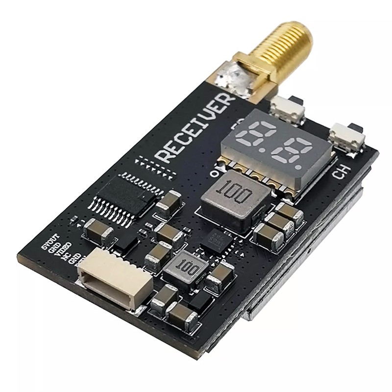
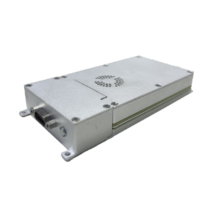
The Kimpok KP-T1250 is an FPV video transmitter module for drone integration. Its nine channels span 1080MHz–1360MHz, with two selectable RF output levels of 25mW and 5000mW and a maximum output of 5W. It supports IRC Tramp control and provides buttons for band/channel selection and power changes. Red, blue and green LEDs indicate channel, band and power respectively. The module accepts DC 7V–36V input with support for 2–8S batteries, and its connections include an MCX antenna interface and a 1.0 6P power connector.
The physical assembly combines an aluminum alloy shell, heat sink and fan within dimensions of 38mm × 38mm × 20.7mm. Mounting holes use 30.5mm × 30.5mm spacing with a specified diameter of 3.0mm, and a cooling fan power cable holder is provided. Installation needs clearance for air convection around the module: inadequate heat dissipation can activate protection that reduces transmit power or stops transmission. Before applying power, check voltage and polarity and fit the RF antenna. The stated weight is 38, without a specified unit.
Specifications
| Specification | Value & conditions |
|---|---|
| Manufacturer brand | Kimpok |
| Model | KP-T1250 |
| Place of origin | China |
| Certification | CE Cerfication |
| Product type | FPV video transmitter module |
| Channels | 9 channels |
| Frequency range | 1.2G; 1080MHz-1360MHz |
| Maximum RF power | 5W; selectable 25mW/5000mWTwo adjustable output power levels. |
| Input voltage and battery support | DC 7V-36V; supports 2-8S battery input |
| Antenna connector | MCX |
| Control protocol | IRC Tramp |
| Cooling architecture | Aluminum alloy shell, heat sink and fan |
| Mounting hole spacing and diameter | 30.5mm*30.5mm /ø3.0mm |
| Dimensions | 38mm*38mm*20.7mm |
| Weight | 38; unit unspecified |
| Channel indicator | Red LED |
| Band indicator | Blue LED |
| Power indicator | Green LED |
| Band and channel control | Band and channel changer button |
| Power control | Power changer button |
| Power connector | 1.0 6P power connector |
| Cooling fan cable provision | Cooling fan power cable holder |
| Thermal protection behavior | Insufficient cooling can trigger overheating protection, reducing transmit power or stopping transmission.Installation must provide space for air convection around the module. |
| Electrical connection precautions | Check input voltage and polarity to avoid component damage.Before applying power. |
| Antenna connection precaution | Fit an antenna to the RF output before powering the module.Before applying power. |