Product overview
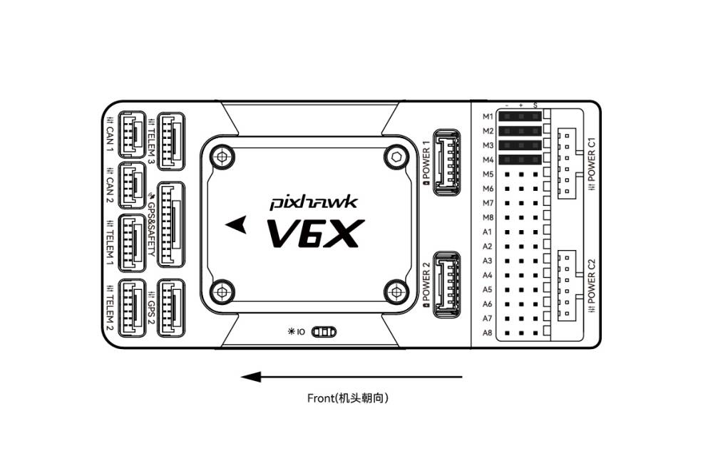
The CUAV Pixhawk V6X Flight Controller is a vehicle-control component whose documented connections support navigation, radio reception, telemetry and actuator integration. Its output architecture separates IO PWM connections at M1–M8 from FMU connections at A1–A8. The latter can be defined as PWM or GPIO, support Bdshot, and serve equipment such as camera shutters, hot shoes and servos. The supplied wiring guide describes hardware connections.
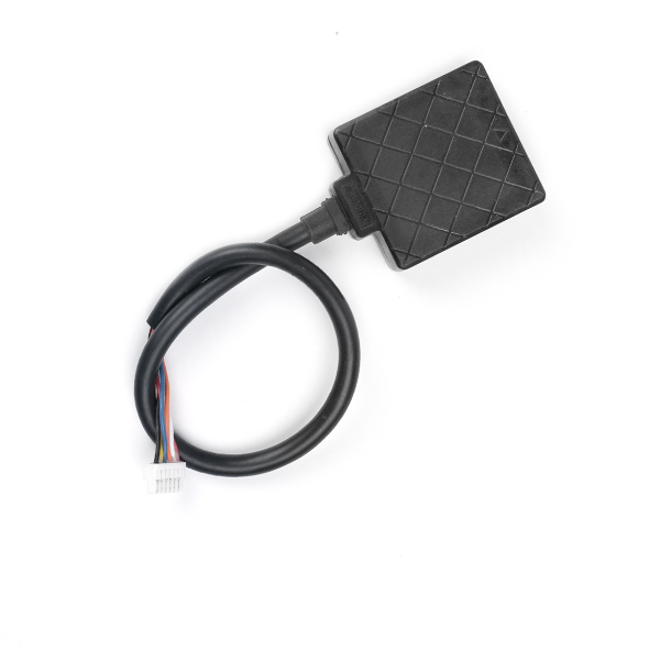
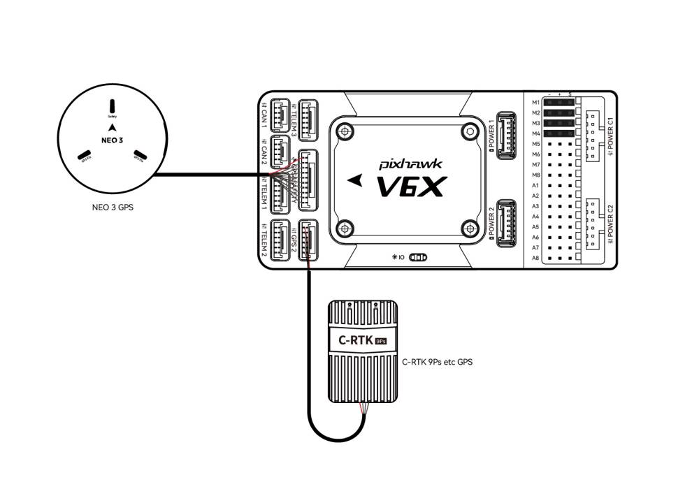
Peripheral integration includes GPS and safety connections, a second GPS/RTK connection, three telemetry interfaces, customizable UART 4, and CAN connections for DroneCAN/UAVCAN devices. Ethernet supports connections to equipment such as task computers, while USB enables computer communication and firmware loading. Installation planning must account for orientation and separation: mounting the controller outside its recommended orientation requires corresponding autopilot configuration. The GPS module should sit on a bracket away from other electronics and face the vehicle front; specifically for NEO GPS, its arrow should point in the same direction as the controller arrow.
A factory-installed logging SD card and a supplied CAN PMU lite module supporting 3–14s lithium batteries through a 6-pin connection to POWER C1 / POWER C2. The interface table instead names CAN PMU SE, so the selected power-module configuration needs confirmation. Power-module setup is firmware-dependent: ArduPilot is described as plug-and-play without additional setup, while PX4 requires the referenced configuration. Motor and servo wiring follows the selected vehicle’s output order. The controller supplies no servo power; an external BEC must feed the positive and negative terminals of an M1–M8/A1–A8 port.
Specifications
| Specification | Value & conditions |
|---|---|
| POWER C1 | Connection for CAN PMU SE / UAVCAN power module. |
| POWER C2 | Connection for CAN PMU SE / UAVCAN power module. |
| POWER 1 | SMbus (I2C) power-module connection. |
| POWER 2 | SMbus (I2C) power-module connection. |
| GPS&SAFETY | Neo series GPS / C-RTK 9PS connection, including GPS, safety-switch and buzzer interfaces. |
| GPS2 | GPS/RTK-module connection. |
| UART 4 | Supports user customization. |
| TELEM1/TELEM2/TELEM3 | Connections for telemetry or MAVLink devices. |
| TF CARD | SD card for log storage; factory-installed.The logging card is pre-inserted at the factory. |
| M1–M8 | IO PWM outputs for ESCs and servos. |
| A1–A8 | FMU outputs configurable as PWM/GPIO; support Bdshot and connections such as camera shutter/hot shoe and servos.These FMU outputs can be defined as PWM/GPIO. |
| USB | Computer communication connection, including firmware loading. |
| CAN1/CAN2 | Connections for DroneCAN/UAVCAN devices, with NEO3 Pro given as an example. |
| DSM/SUB/RSSI | DSM satellite-receiver input, SBUS remote-control-receiver input and RSSI signal-strength return-module input.The table labels the interface DSM/SUB/RSSI; its description identifies DSM, SBUS and RSSI functions. |
| PPM | PPM RC-receiver connection. |
| ETH | Ethernet connection for devices such as task computers. |
| AD&IO | Two analog inputs: ADC3.3/ADC6.6; generally not used.The manufacturer describes these analog inputs as generally unused. |
| Supplied power module and battery support | CAN PMU lite module supporting 3–14s lithium batteries; 6-pin connection to POWER C1 / POWER C2.The power section identifies CAN PMU lite as supplied, while the interface table specifies CAN PMU SE; confirm the selected module. |
| Firmware-dependent power setup | ArduPilot power-module operation is described as plug-and-play with no additional setup; PX4 requires the referenced power-module configuration.Applies to the power-module setup with the stated firmware. |
| Controller mounting orientation | Configure the actual controller mounting orientation in the autopilot software.Required when installation differs from the recommended/default controller orientation, including because of space constraints. |
| GPS mounting | Mount the GPS module on a bracket away from other electronics and facing the vehicle front. Align the NEO GPS arrow with the controller arrow.Bracket placement and forward orientation apply to GPS-module installation; the arrow-alignment instruction specifically identifies NEO GPS. |
| Motor and servo wiring order | Connect motors and servos to M1–M8/A1–A8 in the vehicle-specific order.Output order depends on the selected vehicle. |
| Servo power limitation | The controller does not power servos; connect an external BEC to the positive and negative terminals of any M1–M8/A1–A8 port.An external BEC is required to supply servo power. |
Request a quote for CUAV Pixhawk V6X Flight Controller
Send your application, destination country and expected quantity to the ChinaDrone team. We can discuss product selection, configuration and sourcing from China.
Submit your procurement requirements ↗No account needed. A model number is optional. Your enquiry is handled by ChinaDrone.