Product overview
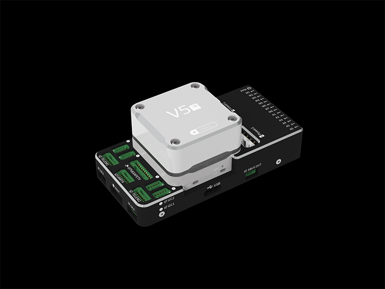
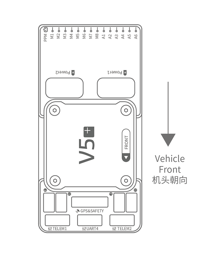
The CUAV V5+ is a flight-controller integration product whose documented architecture centers on power, peripheral and actuator connections. POWER1 handles power-module input and voltage/current detection, while POWER2 accepts an I2C smart battery. The M1~M8 and A1~A6 PWM outputs provide motor or servo connections, with wiring order determined by the selected vehicle’s Airframe Reference. I2C and UAVCAN interfaces accommodate devices such as external compasses and CAN GPS, while USB Type-C provides computer communication for tasks including firmware loading.
For procurement, the documented supplied configuration includes an HV_PM power module supporting 2~10s LiPo batteries, a dedicated safety switch, an SBUS cable and a factory-inserted SD card. The power-wiring instruction subsequently calls the module HW_PM, so the supplied module identification needs confirmation. NEO v2 GPS is recommended and combines positioning, compass, safety switch, buzzer and status light functions. Controller hardware and wiring rather than a complete flight platform or an airframe-only kit.
Installation planning must account for controller orientation and GPS/compass placement. If space constraints require a different controller orientation, the software must reflect that mounting; the GPS/compass should sit away from other electronics with its direction marker facing forward. Without GPS, the safety switch must connect directly to GPS1 for arming and flight. Using another GPS may require an external buzzer. Manual control requires a compatible, bound RC system; optional telemetry connects through TELEM1/TELEM2.
Specifications
| Specification | Value & conditions |
|---|---|
| Product purpose | CUAV V5+ flight controller for integration with vehicle power, sensors and peripherals. |
| POWER1 | Power-module connection for power input and AD voltage and current detection.Connect the power module to POWER1 as directed by the wiring guide. |
| POWER2 | Connection for an I2C smart battery. |
| TF CARD | SD-card slot for log storage.The SD card is inserted at the factory. |
| M1~M8 | PWM outputs for motor or servo control.Connect motors and servos in the order specified for the selected vehicle in the Airframe Reference. |
| A1~A6 | PWM outputs for motor or servo control.Connect motors and servos in the order specified for the selected vehicle in the Airframe Reference. |
| DSU7 | FMU debugging and debug-information access. |
| I2C1/I2C2/I2C3/I2C4 | Connections for I2C devices, including an external compass. |
| CAN1/CAN2 | Connections for UAVCAN devices, including CAN GPS.Use the CAN interface when connecting CAN GPS. |
| TYPE-C(USB) | Computer communication connection, including firmware loading. |
| SBUS OUT | Connection for an SBUS camera gimbal. |
| GPS&SAFETY | NEO GPS connection incorporating GPS, safety-switch and buzzer interfaces.Recommended combination: NEO GPS; CAN GPS uses the CAN interface. |
| TELEM1/TELEM2 | Connections for the telemetry system.Telemetry is optional; a vehicle radio connected to TELEM1/TELEM2 requires no further configuration. |
| DSM/SBUS/RSSI | DSM satellite-receiver input, SBUS remote-control receiver input and RSSI signal-strength return input.Select a compatible transmitter and receiver and bind them for manual control. |
| Included power module and battery support | HV_PM power module included; supports 2~10s LiPo batteries. The guide directs a 6-pin power-module connection to POWER1.Published battery support applies to the included HV_PM module. The following connection instruction names HW_PM; confirm the supplied module identification. |
| Included safety switch | Dedicated safety switch supplied with V5+.The dedicated switch is required when the recommended NEO GPS with its built-in safety switch is not used. |
| Safety-switch connection without GPS | GPS1 safety-switch connection required for operation without GPS.Without GPS, attach the switch directly to GPS1 to enable arming and flight. |
| Included receiver cable | SBUS cable included in the kit. |
| Factory-installed SD card | SD card inserted at the factory. |
| Controller mounting orientation | Configure controller software to match the actual mounting orientation.Applies when mounting differs from the recommended/default orientation, including changes caused by space constraints. |
| Recommended GPS module | NEO v2 GPS with GPS, compass, safety switch, buzzer and LED status light.Recommended module configuration; inclusion in the V5+ kit is not established. |
| GPS/compass installation | Frame-mounted GPS/compass with separation from electronics and forward-facing orientation.Keep the GPS/compass away from other electronics and align its direction marker with the vehicle front. |
| Buzzer limitation | Buzzer operation may require an external buzzer.Applies when the recommended GPS is not used. |
| Radio-control requirement | RC radio system required for manual vehicle control; PX4 autonomous flight modes do not require a radio system.Manual control requires an RC system; the stated autonomous-flight exception applies to PX4. |
| Motor and servo wiring | Motor and servo connections use MAIN and AUX ports with vehicle-specific ordering.Apply the motor/servo ordering specified for the selected vehicle. |
Request a quote for CUAV V5+ flight controller
Send your application, destination country and expected quantity to the ChinaDrone team. We can discuss product selection, configuration and sourcing from China.
Submit your procurement requirements ↗No account needed. A model number is optional. Your enquiry is handled by ChinaDrone.