Product overview
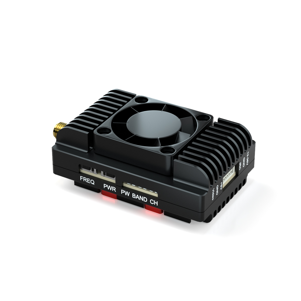
The Kimpok AL1204 is an FM FPV video transmitter for RC drone image transmission. Its hardware combines PLL frequency control, selectable transmission power and a built-in power filter in a unit measuring 44 × 28.6 × 14.7mm and weighing 25.3g. Integration requires space for the transmitter, a suitable antenna connection and a DC 7-30V (2-8S) supply. The video input is specified at 1V±0.2Vp-p typical, while the SMA antenna interface is rated at 50 Ohms.
The transmitter provides 16 channels across two eight-channel bands within 1080-1360MHz, with PIT, 25mW, 200mW, 1W and 4W settings. A single RGB-lit button selects band, channel and power; IRC Tramp control and a DATA pin support flight controller setup. Installation must secure the unit while avoiding vibration and high temperatures. An antenna must be connected before operation to prevent possible damage, and excessive supply interference must be avoided despite the built-in filter. The operating temperature range is -10 °C to +70 °C.
Specifications
| Specification | Value & conditions |
|---|---|
| Manufacturer | Kimpok |
| Model | AL1204 |
| Place of origin | China |
| Certification | CE |
| Product type | FPV video transmitter |
| Frequency band | 1080-1360MHz |
| Frequency precision | ±200KHz (Typ.)Typical frequency precision. |
| Channel count | 16 CH |
| Output power settings | PIT/25mW/200mW/1W/4W |
| Modulation | FM |
| Power supply | DC 7-30V (2-8S) |
| Frequency control | PLL |
| Video input level | 1V±0.2Vp-p (typ.)Typical video input level. |
| Signal-to-noise ratio | Greater than 55dBcFor ±3MHz. |
| Control protocol | IRC Tramp |
| Antenna interface | SMA 50 Ohms |
| Operating temperature | -10 °C to +70 °C |
| Dimensions | 44 × 28.6 × 14.7mm |
| Weight | 25.3g |
| Band A frequencies | 1080, 1120, 1160, 1200, 1240, 1280, 1320, 1360MHzBand A, channels CH1 through CH8 in order. |
| Band B frequencies | 1200, 1220, 1240, 1258, 1280, 1300, 1320, 1340MHzBand B, channels CH1 through CH8 in order. |
| Antenna connection requirement | Connect the antenna before use; operating without it risks product damage.Before use. |
| Mounting requirements | Mount securely and avoid vibration and high temperatures.When mounting the transmitter. |
| Power filtering | Built-in power filter; excessive power supply interference must still be avoided. |
| Controls and indicators | Single button with integrated RGB lighting: blue indicates band, red indicates channel, and green indicates power level.Local button control. |
| Status indication | Cyclic RGB blink counts indicate transmitter status; a continuously lit green LED indicates PITMODE.When there is no operation. |
| Setting procedure | Long-press to enter settings, release at the relevant indicator color to select a function, then short-press to change its value.Local button setup. |
| Flight controller connection | Connect the DATA pin for flight controller setup.For setup via a flight controller. |