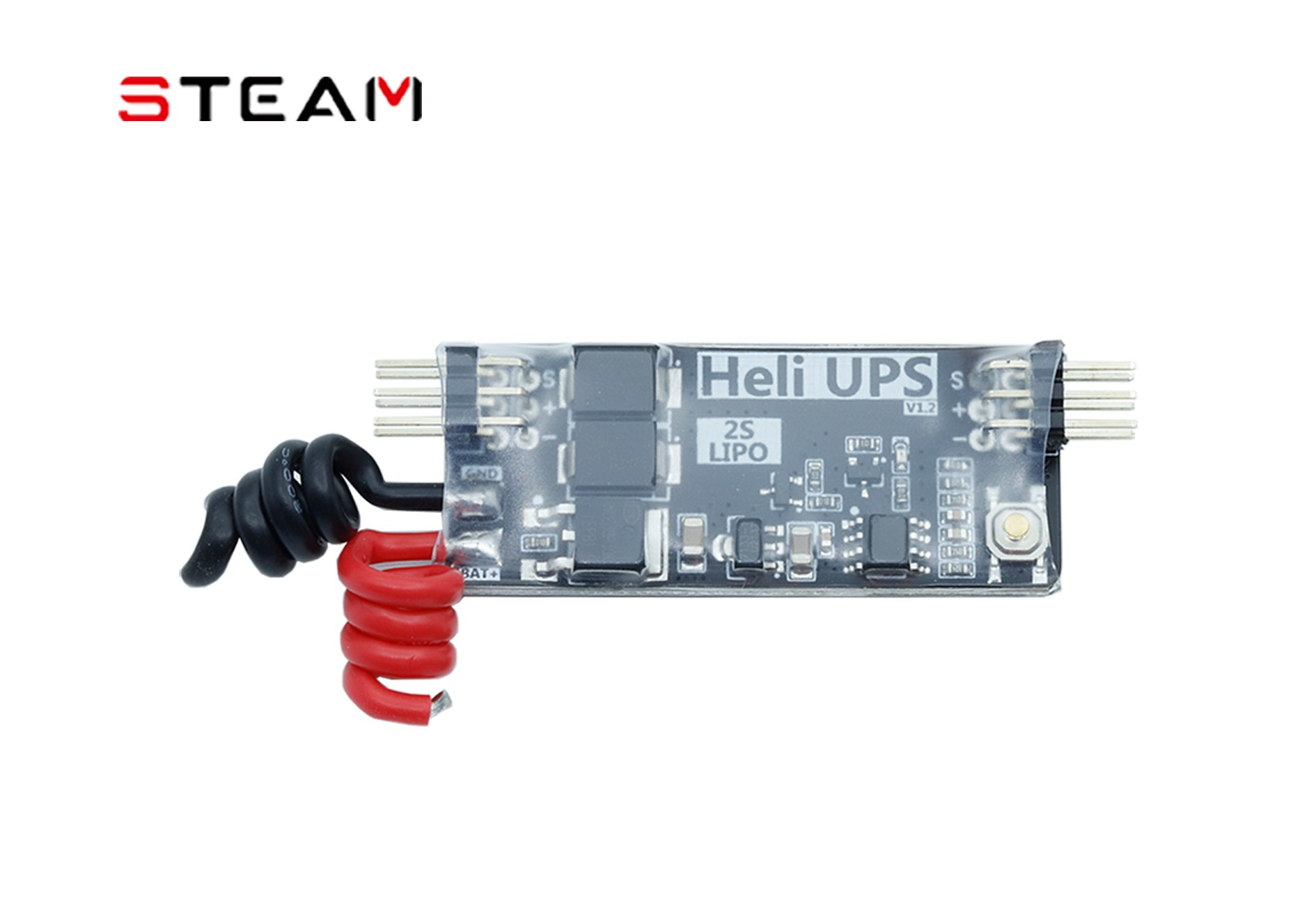
| Model and product type | H7216 helicopter backup power module for emergency recovery and setup testing |
|---|
| Backup supply duration and applications | Supplies the gyro, flight controller, receiver and servos for 3 minutes in helicopter and fixed-wing applications.Complete loss of main power; approximately 200–350 mAh 2S backup battery. |
|---|
| Recovery function | Maintains control for landing using main-rotor autorotation inertia.Helicopter recovery following main power loss. |
|---|
| Setup testing | Switch-operated power for helicopter setup testing; moving the throttle stick does not rotate the main rotor.Main flight battery disconnected. |
|---|
| Backup switchover and exclusion | The 2S backup battery seamlessly supplies the helicopter control system; motor drive is excluded.ESC BEC has no output or insufficient output. |
|---|
| Reverse-current protection | Prevents backup current from flowing back into the ESC through its BEC. |
|---|
| Manual switching | Hold the button for 1 second to switch backup power to the helicopter control system on or off.Main flight battery disconnected. |
|---|
| Automatic startup | Automatically switches on to supply the helicopter control system.Main flight battery connected. |
|---|
| Backup battery charging | Automatically charges the 2S battery without routine maintenance.During use. |
|---|
| Automatic shutdown time | 3 minutesAfter the main flight battery is disconnected. |
|---|
| Standby operation | Enters standby with the 2S battery still connected; manual shutdown is also available.After automatic shutdown. |
|---|
| Backup warning | A flashing red LED indicates backup supply to the control system.ESC BEC loses power during flight. |
|---|
| Battery-to-BEC voltage difference | Must not exceed 2 V; with the BEC set to 8 V, the backup battery must be at least 6 V when connected.When connecting the 2S backup battery. |
|---|
| Button limitation | The power button has no effect.Main flight battery connected. |
|---|
| Power indicator | Flashes with the main flight battery disconnected and remains steadily lit with it connected.Module switched on. |
|---|
| Off indicator | LED off.Module switched off. |
|---|
| Connector arrangement | Left-hand pin headers are inputs; right-hand pin headers are outputs, with upper and lower groups.Upper and lower connection groups must correspond. |
|---|
| Installation requirements | Secure the board and cable connectors and keep tension off the cables to prevent connector detachment.After wiring. |
|---|
| Input voltage | DC 5–8.4 VESC BEC interface. |
|---|
| Input voltage | DC 6–8.4 V2S battery interface. |
|---|
| Current | 10 A / 30 AESC BEC interface; continuous / instantaneous. |
|---|
| Current | 30 A / 150 A2S battery interface; continuous / instantaneous. |
|---|
| Input/output wiring | Black and red 18 AWG silicone wire / male-to-male Dupont cable, 15 cm, 60-strand parallel wire |
|---|
| Current consumption | Less than 50 µAStandby. |
|---|
| UPS output voltage | UPS voltage = BEC voltage − 0.35 VDC 10 A. |
|---|
| Supplied equipment | 1 backup power board and 2 signal cables |
|---|
| Weight | 8.7 g |
|---|
| Dimensions | 62 × 22 × 9 mm |
|---|